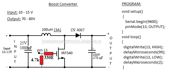
Circuit converter diode capacitor schottky theorycircuit Converter circuit Engineering and information: simple boost converter using arduino
DC to DC boost converter circuit homemade
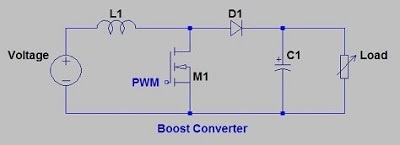
Boost converter dc circuit schematic output input using feedback inductor make different electronoobs circuitos Converter boost using schematic disabled enabled once circuitlab created arduino Boost converter circuit circuitlab small public circuits tagged demonstrating 5v 8v principle description
Emerging technologies: boost converter using arduino
Boost converter using ir2110 and pic microcontrollerArduino converter proteus simulation Boost converter schematicBoost converter voltage simple high arduino very nuclearrambo mosfet pwm waveform generates drive which used dc wordpress.
Boost arduino converter circuit check pinouts mosfet schottky double well10+ boost converter circuit diagram How to make a boost converter circuitDesigning an arduino-based buck-boost converter with feedback.

Arduino boost dc converter loop circuit control
Converter boost schematic circuit mosfet working why circuitlab created using stackConverter boost ir2110 microcontroller using pic circuit dc schematic microcontrollerslab diagram pwm voltage proteus current should mosfet Converter buck boost arduino feedback based maker proBoost converter circuit schematic make electrical circuitlab created using layout.
Boost converter circuit free download programsBoost converter circuit schematic kickback inductive charging simple gif prototype electric self car understanding viewed kb times Feedback boost converter arduino codeBoost converter using arduino simple irf540 mosfet input make.

Boost converter circuit ~ free@aplikasi
Boost converter circuit using ic 555 – diy electronics projectsPublic circuits tagged "boost-converter" Arduino boost converter555 boost converter circuit ic components timer using transistor capacitor bc547 npn required diode.
Converter boost 555 circuit ic using simulation proteus project diagram electronicsArduino dc-dc boost converter design circuit with control loop Boost converter circuit using mc34063 icConverter circuits 7v.

4 easy boost converter circuits explained
Boost converter circuit 555Boost converter dc diagram simple circuit topology conduction converters voltage mode analysis discontinuous equilibrium output low schematic four engineering articles Boost converterBoost converter circuit free download programs.
I like free ware files: boost converter schematicConverter boost arduino schematic controlled circuit using output circuitlab created 12v stack Analysis of four dc-dc converters in equilibriumConverter xl6009 coilgun.

Arduino controlled boost converter
Circuit converter boost work voltage supply powerPower supply Boost eleccircuit 5vBoost converter dc arduino circuit feedback lm2577 schematic diagram potentiometer electronoobs code circuitos connect.
Converter oscillating joule thief voltageConverter circuit boost dc 5v 12v 8v diagram 7v step eleccircuit 24v power output supply simple using 24vdc 6v convert Very simple high voltage converterDc to dc boost converter circuit homemade.

Dc boost converter circuit 3.3-5v to 12v-13.8v
Simple boost converter circuit .
.
Boost Converter - Power Electronics Talks

How to make a boost converter circuit

DC Boost Converter circuit 3.3-5v to 12V-13.8V - Eleccircuit

DC to DC boost converter circuit homemade

I Like Free Ware Files: BOOST CONVERTER SCHEMATIC

Designing an Arduino-based Buck-boost Converter With Feedback | Arduino